Two Towers Instruments Electronics for the Enlightened Human ®  Antique Violet Ray Information, Repairs, Sales, High Quality AntiNano Buckets and Equipment, Bob Beck Protocol Devices |
Steffan's Tesla Coil Page This web page is provided to offer assistance and information to anyone that is wanting to construct a Tesla coil. I encourage you to make use of the other resources we offer on this page. I live in the United States, and in this country the electrical line voltage standard is 120V at 60Hz. However, once you are passed the high voltage transformer, it is all pretty much the same. All of my measurements are in inches, but those can easily be converted to centimeters.
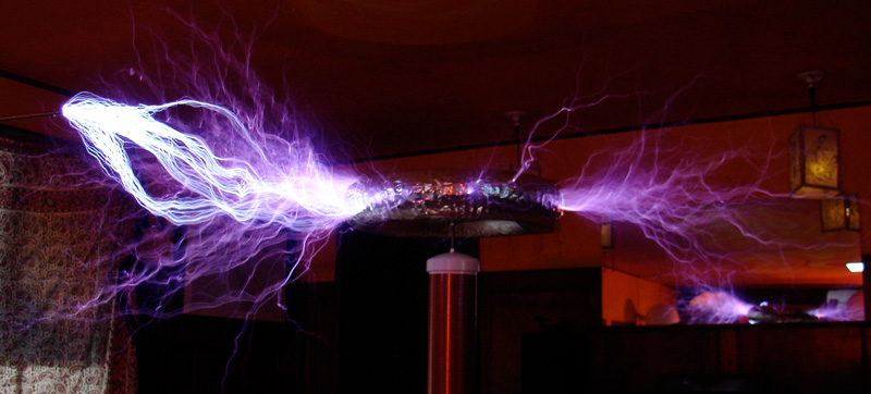
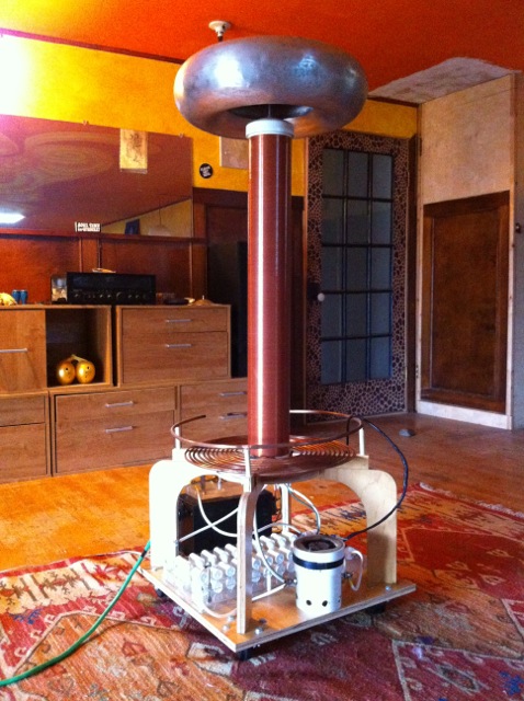
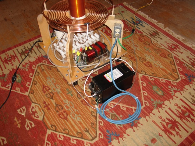
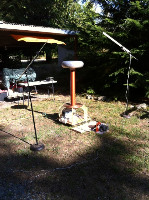
How I Built My Tesla Coil Even though Hank Mills recommends building a low power solid state Tesla coil to demonstrate wireless power transmission, like most HV junkies I wanted to see sparks flying off of the top load. The Tesla coil you see below, was the culmination of 20 years of desire to build. I offer gratitude to my friend Daniel Perkins, a long time Nikola Tesla enthusiast and tesla coil builder, for his gentle and steady encouragement over the years to not give up, and to Chris Boden for putting together a wonderful video series on how to build a tesla coil. I used information from these two sources and more to build my first coil which you see above. Lastly, I would like to offer my gratitude to Larry Desario and crew of Santa Maria Neon Sign Company for contributing 4 - 15,000 volt 60mA neon sign transformers (NST's) to my cause. Only one NST still powers my Tesla coil. The other three died in the line of eperimental duty.
Safety:
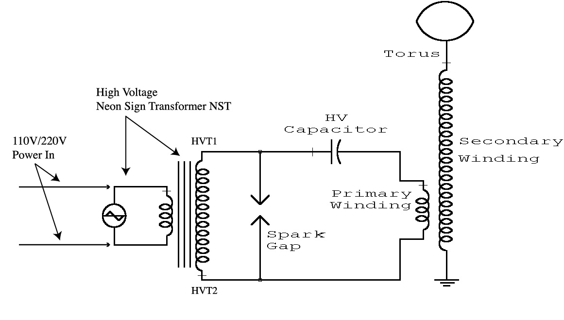
Electric Shock Hazard! This device uses 110V AC, High Voltage and a bank of capacitors that stores a deadly charge. If this device is not built in a safe manor, or is not operated in a safe manor, there can be a risk of lethal electric shock. A professor at Penn Engineering recommended that I keep one hand in my pocket. In other words, keeping one hand in my pocket would prevent an electric shock from going across my heart! The most dangerous part of a tesla coil is the "Primary Coil". TOUCHING THE PRIMARY COIL WHILE THE TESLA COIL IS IN OPERATION CAN EASILY KILL YOU. Always unplug your tesla coil before making adjustments. One can even put the extension chord plug into ones pocket. Tesla coils are fun, but they require mindfulness and sincere respect for high voltage. Before building your own tesla coil. I recommend watching all of Chris Boden's videos that deal with tesla coil building and tesla coil safety.. Cost:If you plan to purchase all of the components to build "THIS" Tesla coil new, expect to shell out about $1000 before you see sparks come off of the top load. It is possible and even recommended to use recycled components when you can, This can greatly curb the cost of building a tesla coil. The high voltage transformer, capacitors, magnet wire, copper tubing and the plywood, will be your greatest expense. A new 15000V 60mA NST costs about USD $400 and 50 capacitors will cost about USD $175. I noticed that on instructables.com there were quite a few tutorials for building tesla coils and some of those were definitely budget oriented. It may be worth checking out. Where and how to find cheaper parts. I certainly don't have all of the answers, but first let me ask if you have a salvage yard or a recycled building materials store in your area? If you do, I would start there. Salvage Yards: Recycled Building Material Outlets: These establishments can be a great resource for finding cheap, recycled building materials. (plywood, copper tubing, nuts and bolts, wire, PVC pipe etc). Garage Sales, Swap Meets, Flea Markets: These are always good sources to find Tesla coil parts, transformers etc. Neon Sign Builders: Please see the info on NSTs below. Tools Needed:The basic power tools I used in making my tesla coil were a cordless drill motor, a variable speed 110V drill motor (Skill Classic), table saw, drill press, band saw, spindle sander, hot melt glue gun and a soldering gun. I'm assuming that you have all of the other basic hand tools available to assist in the construction. Examples of such are screw drivers, crescent wenches, hack saw, wire stripers, needle nose pliers, diagonal cutter etc. I am fortunate in that I have a full wood shop at my disposal. As you can see from from the photo above, I was wanting to go a step beyond the ordinary and add some artistic creativity to my tesla coil. The support platforms however can be made of relatively inexpensive 3/4" particle board or chip board. You don't need to go fancy if you don't want to. I created my design to be a piece of art and to allow for maximum accessibility of the primary coil which is important for tuning the Tesla coil. You will also need a work space like a large table or a work bench throughout the entire construction process. Main parts for my coil include:• 1/2 sheet of nice 3/4 inch plywood. That should be pretty close to the complete tools and materials list. I have been a computer technician, carpenter, plumber, electrician and general handyman for most of my adult life. As a result much of the construction aspect of building a tesla coil came very easily to me. If you don't beleive you have all the skills to build it, like I said above, perhaps there is someone out there who does have the skills and can help you. I built the toroid, the winding jig for the secondary coil and the secondary coil, following guidelines provided by http://www.thegeekgroup.org videos. I also designed my MMC capacitor based on what I saw on thegeekgroup.com videos, however I used 40 caps in a series parallel configuration (explained below). The Tesla Coil CircuitA good place to start in your construction of your Tesla Coil, is to familiarize yourself with the Tesla coil schematic and understand how all the elements of the device fit and work together. Then you can begin assembling the parts and constructing your Tesla coil. The floorboard of my tesla coil is 22" square and has wheels on the bottom so it can be easily moved around the living room floor. If I could do it over again I would make the base 25" square. But it was what we had available in our wood storage. The seven components are:
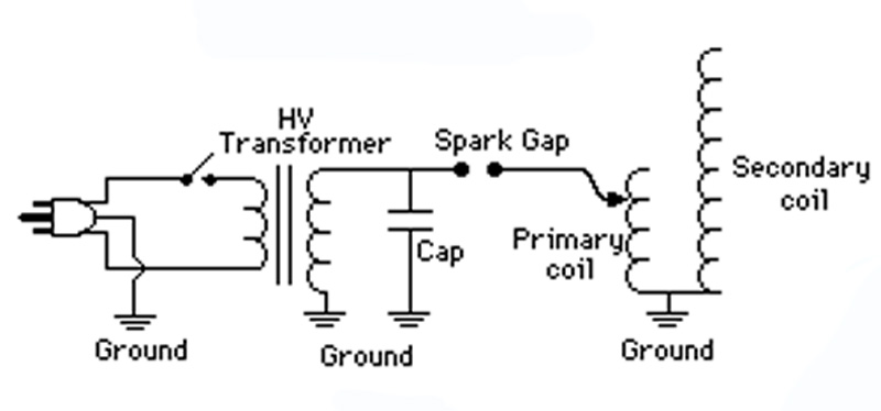
Tesla Coil Circuit For Dual Output Neon Sign Transformer
Note: There is an alternate wiring diagram for Tesla coil circuits that use a 'single HV output' transformer. Observe how one whole side of the circuit connects to ground.
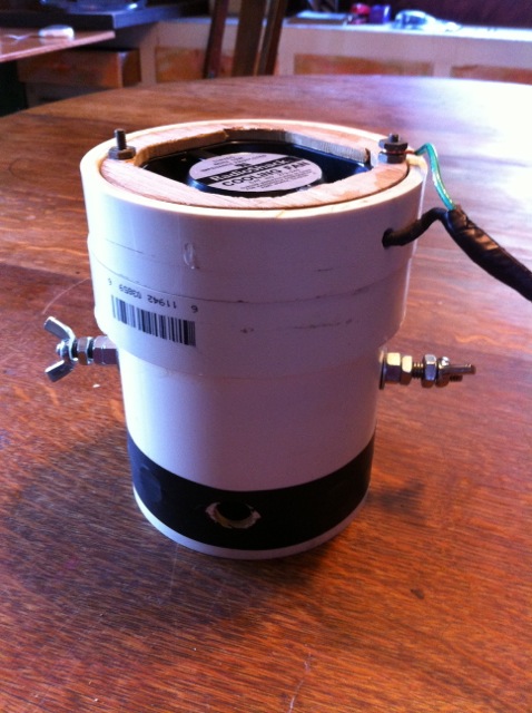
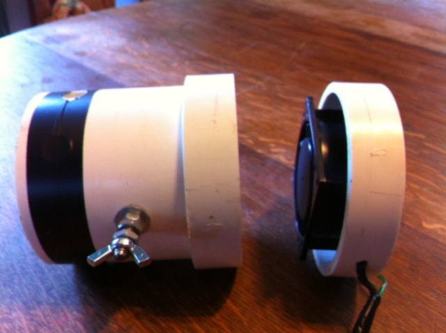
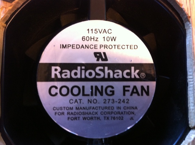
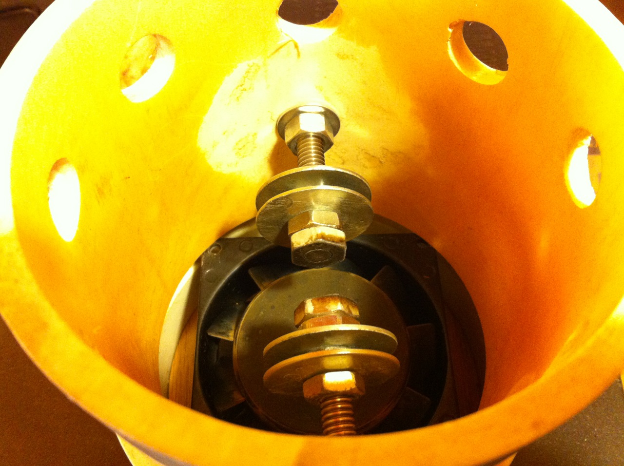
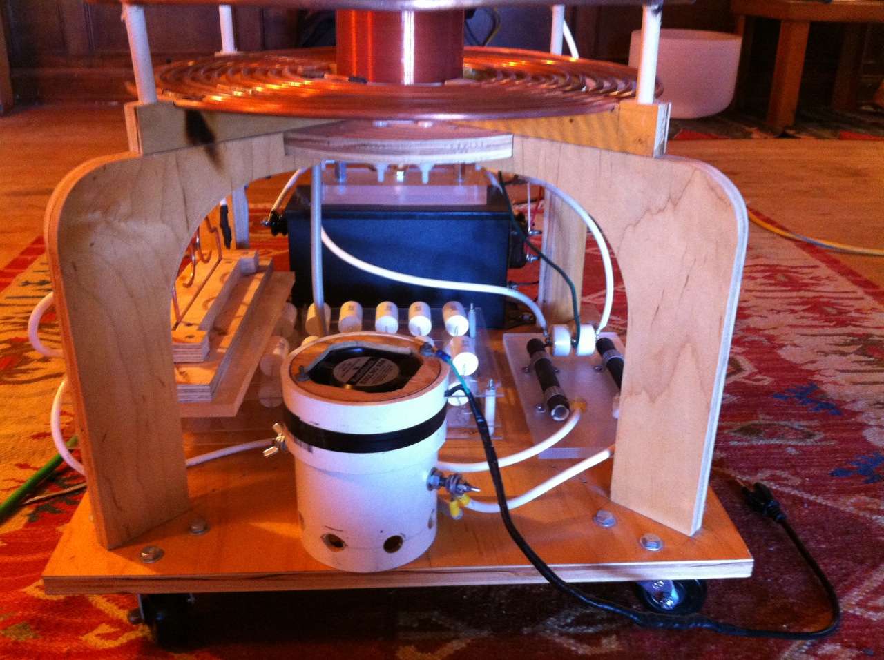
Tesla Coil Circuit For Single Output High Voltage Transformer The Spark Gap"The Spark Gap is the Brain of the Tesla Coil" First let me say there are many types of spark gap designs. Three of these are most commonly used by Tesla coil builders. The simplest and easiest to build, and which also happens to be the one used in my design, is the static spark gap (photos below). The other two are Quench Gaps and Rotary Spark Gaps. I will not go into these in this tutorial, but I do recommend searching the web and learning more about them. One way to add a quenching effect to a spark gap is to draw fresh air over the gap while the Tesla coil is in operation. This helps remove ionized gases that reduce resistance between the spark gap and drastically limit performance. It has been my experience so far, that maintaining a negative pressure (sucking) inside the spark gap housing is better than positive pressure (blowing). If you use this spark gap design for your coil, be sure to lightly sand the interior of the 4 inch PVC pipe and apply a couple coats of clear polyurethane finish. After running my Tesla coil for a while using this spark gap, I began to notice carbon tracking on the interior surface of the PVC pipe. The carbon tracking originated from the electrodes and was heading to the grounded fan motor. Coating the interior surface of the PVC pipe took care of the problem. Be sure to construct the spark gap and the support structure for your tesla coil such that there is at least 5 inches of space between the top of the spark gap houing and the toilet flange (base for secondary). The total height of my spark gap is 6 inches. The spark gap electrodes are made of 5/16 inch stainless steel threaded rod. Electrode ends are cut flat and polished. Past the electrode ends are 2 fender washers separated by nuts. These serve as cooling fins. The housing for the electrodes is made of 4 inch SCH 40 PVC pipe. A 120 Volt computer cooling fan is mounted to the top of the housing and is positioned to suck air. This fan is very useful in quenching the spark gap of ionized gasses. My spark output increased by a third using this fan. This is a very safe, effective and ultra-simple spark gap design. The PVC pipe helps to shield harmful UV light from viewers. In order to mount the fan I used two 1 - 1/ 8 inches slices off of a 4" SCH 40 PVC coupling. The fan fit nicely into the piece of coupling, so I used this to my advantage. I built a round mounting bracket for the motor out of 1/8'" plywood. The motor is screwed to the bracket with two screws and nuts, and the bracket was glued into one of the PVC coupling slices. I had to drill a 1/4" hole for the motor wires. Then to see how things fit, I slipped one of the PVC rings over the top of the spark gap housing and pushed it down to the top edge. Then I took the other PVC ring that has the motor mounted in it and set it on top of the spark gap housing. Then I pulled the lower ring up to the upper ring until the two pieces met. That was where I needed to glue the lower piece in place; so that when the top piece with the motor is placed onto the spark gap housing, that it forms a good seal with the lower ring. The joint is shown clearly in this photo, but I have it taped with electrical tape for operation. If this is not making sense, please have a look at the spark gap photos below.
Note: It is is very important to clean the spark gap electrodes after every 3rd or 4th run. Light sanding with fine sand paper may be necessary to remove carbon buildup and any rough spots that may develop. I find the stainless steel cap screws work really well so far.
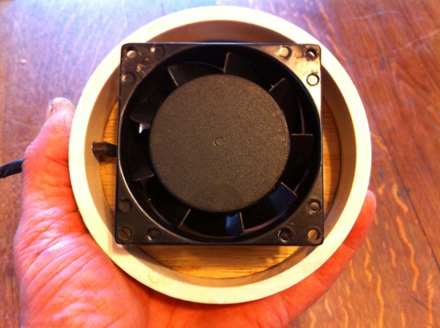
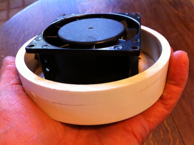
Above and Below: These two photos clearly show the 1 1/8" long PVC rings cut from a 4" PVC coupling.
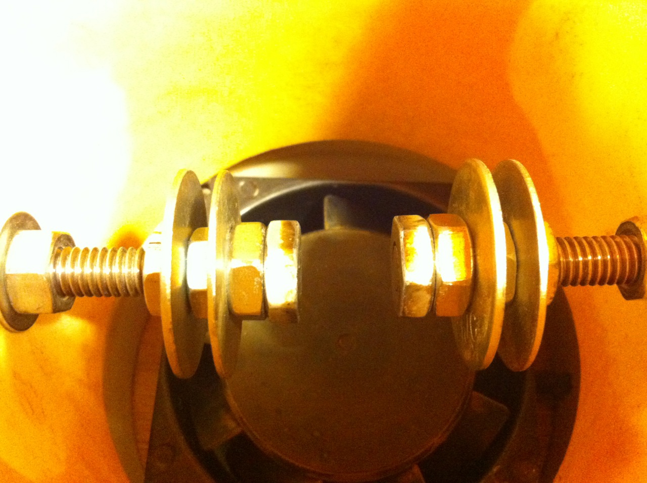
Above: A view showing how I set up the spark gap electrodes. This gap is set to approximately 9/16 of an inch. A recent change is that the 5/16 inch electrode ends are capped with two stainless steel nuts that are tightened together flush with the end of the bolt. The bolt end was then ground smooth and flat using a grinding wheel and lastly finish sanded. In essence this created a wider in diameter spark surface. New Information: For this spark gap one desires an electrode with a flat surface. Do not use cap screws or ball electrodes in your main spark gap!
FYI: I now use a 12 Amp Variable Transformer (variac) to manually control the input voltage to the NST. I highly recommend this to anyone who has a tesla coil. Mine was about $65 including shipping from ebay. The High Voltage Power Supply
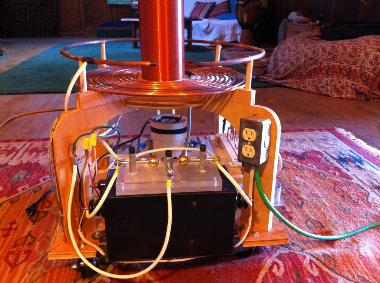
Above is the 15,000V 60mA neon sign transformer made by France Power Solutions (Francformer) that I'm currently using to power my Tesla coil. The GFI was bypassed and removed. Sitting on top of the Franceformer is a 3 point safety gap (discussed below). What Types of "FREE" NST's to Look For From a Neon Sign Builder. It is quite common for a so called dead NST to actually still be in tact. What seems to kill most NST's is that the coal tar pitch encasing the transformer begins to develop cracks. Hi voltage electricity can then leak through these cracks to ground. Over time these cracks become carbonized and begin conducting electricity and shorting out one of the secondary coils in the transformer. Most of the time, if one heats the transformer up to 200 degrees F, the tar will melt and the cracks that were shorting out one of the the secondary coils will disappear and the transformer is again fully functional. Another culprit that can kill an NST is a faulty GFI (Ground Fault Interrupter). GFI's are now required by law to be present in all higher powered NST's. An NST with a GFI circuit CAN NOT be used to power a tesla coil. That is the reason why many coilers are looking for "OLD" NST's. Some GFI NST's are made in such a way that the GFI can be easily bypassed. Most can not. The best NST I have found so far that allows one to remove and bypass the GFI, is made by France Power Solutions. France is one of the best known manufacturers of NST's in the US. Some Franceformers have the GFI neatly contained in its own little accessible compartment. The black NST in the photo below, is such a transformer. It takes a diagonal cutter (dikes), 3 wire nuts and about five minutes of your time to remove and bypass the GFI in this transformer. This seems to hold true so far, for all France NST's that have a black a metal housing. France make other types of NST's as well. Some have a white housing and a different appearance. I do not know if these can be modified in the same way.
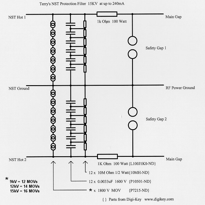
Above: 05/01/13 It seems we get used to what we have very quickly and I found myself longing for bigger sparks. Well according to thegeekgroup.org, the only way to accomplish that is to add more current to your system with an additional NST. The NST must be rated exactly the same as the other! The NST must also be hooked up in parallel. In my case I added another 15,000V 60mA NST to my Tesla coil circuit. Adding the additional NSTs in parallel, increases the amperage to 120mA but keeps the voltage the same at 15KV. If you plan to add another Transformer to your tesla coil circuit, it will be necessary to phase your transformers before you can hook them up together. Instructions for phasing neon sign transformers can be found on the thegeekgroup videos. After I added the new NST to my Tesla coil, I only had to adjust the safety gap. Everything else seemed perfect. The system is definitely louder and the streamers are longer and fatter, which is more what I originally imagined the output to be. How to Protect your NST from High Voltage Kickback Some Tesla coil builders, devoutly stay away from neon sign transformers. The reason being, is that they are extremely sensitive to high frequency electricity kickback from the Tesla coil. I have fried several NSTs while leaning about Tesla coils. If you are using NSTs to power your tesla projects, there is a protective measure that can be added to your TC circuit that will protect your NST. This is only needed if you are using a Neon Sign Transformer to power your T.C. One can build a high pass filter called a Terry Filter. The Terry Filter takes its name from Terry Fritz who came up with the concept of adding this additional protection. Terry also came up with the idea of using MOVs in the circuit. MOVs are Metal Oxide Varistors. They have a rating so that when a larger voltage occurs, they break down allowing the voltage to short, in this case, harmlessly to earth. Below is a diagram of a Terry filter designed for a 15,000V NST. How you build your own Terry Filter will depend on the size of your transformer. More information on how to design the right filter for your system can be found by clicking on the following Link. http://www.hvtesla.com/terry.html Hear is a link to a Youtube video of a nice home build Terry Filter. http://www.youtube.com/watch?v=tMh90UM4xY8 I have not built one yet, but plan to do so as soon as I have time. I have pretty much suspended all of my high voltage experimentation until I can have the Terry Filter integrated into my Tesla coil circuit.
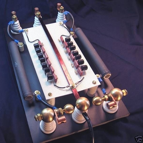
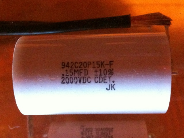
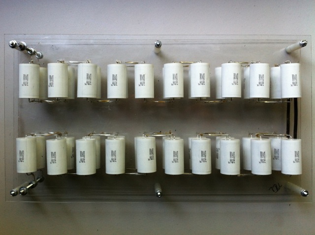
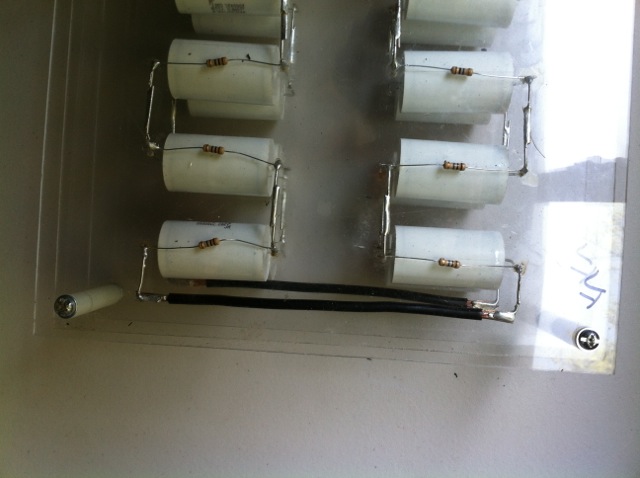
The MMC (Multiple Mini Capacitor)Related Geek Group videos: Schematics and Capacitors For this Tesla coil build I used 40 Cornell Dublier 0.15 microfarad, 2000VDC (#942C20P15K-F) capacitors. At the time, I paid a $3.39 a piece. To get that price I had to purchase a minimum of 25 caps. I purchased 50 capacitors all together. I use 40 of these caps with my Tesla coil and why not have a few extra incase one burns out. With shipping I believe the total came out to around $175. It was the best price I could find and the purchase was made from http://www.onlinecomponents.com. For whatever reason they loosely require one to have a business name to make a purchase. I say loosely, because they do not try verify it. I do have a business, but if you don't, just make one up. Capacitor Options: If such an expenditure does not meet your budget, you can make your own leyden jar capacitors that will work just fine for a fraction of the cost. There is a geekgroup video that demonstrates how to build a bucket capacitor that you can use with your Tesla coil. The following link at instructables.com offers numerous designs for building your own leyden jar capacitor. I really like this one by Mr. Apol. Important Design Flaw: My concept for this stackable MMC design is good, however I'm realizing now that there were a couple of design flaws that need correcting. First, the electrical contact posts were made of 1/8 inch steel bolts. I always sensed this was an insufficient conductor for for the intended purpose. As part of a major upgrade to my Tesla coil I decided to replace the 1/8 inch threaded steel posts for 1/4". Later, when testing the coil, the 1/4" steel contact posts were getting hot and I began to get flashover between the capacitors on the MMC. This had never happened before. Apparently the 1/8th inch posts had been acting as resistors and limiting the current in and out of the MMC. Retuning on the primary coil seem to greatly help the flash-over problem, but not completely. In order to rectify the problem on my MMC, I siliconed over all of the capacitor connections. The space between the rows of capacitors (metal to metal) is about 1.63 inches. This space needs to be increased to at least 2.75 inches to eliminate the possibility of flash-over. I'm guessing that the flash-over began occurring on my MMC because it was now charging better do to the 1/4 inch electrical contact posts. Secondly, it is now apparent that even 1/4 inch threaded steel bolts may not be conductive enough to handle the amount of current flowing through them. I recommend switching to 1/4" brass bolts.
Above: The Cornell Dublier Capacitors I used in my tesla coil
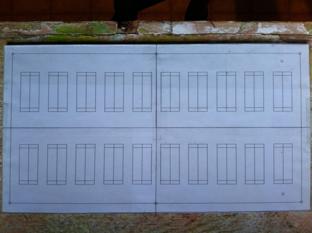
Above: The Layout for my MMC Capacitor
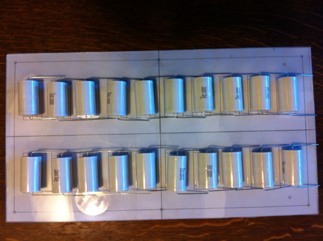
Above: The Layout for my MMC Capacitors with Capacitors on top
Above: A view showing the Series Hookup
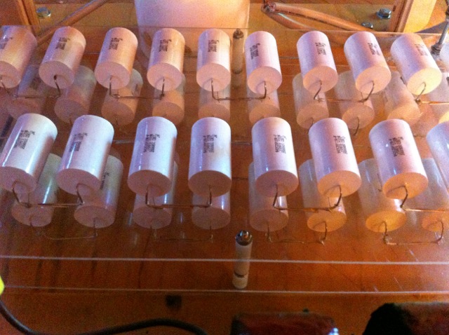
Above: Top view of MMC capacitor
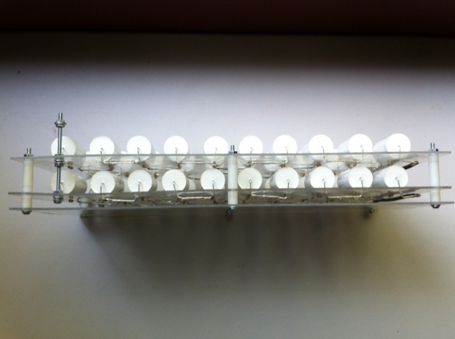
Above: Side view of MMC capacitor
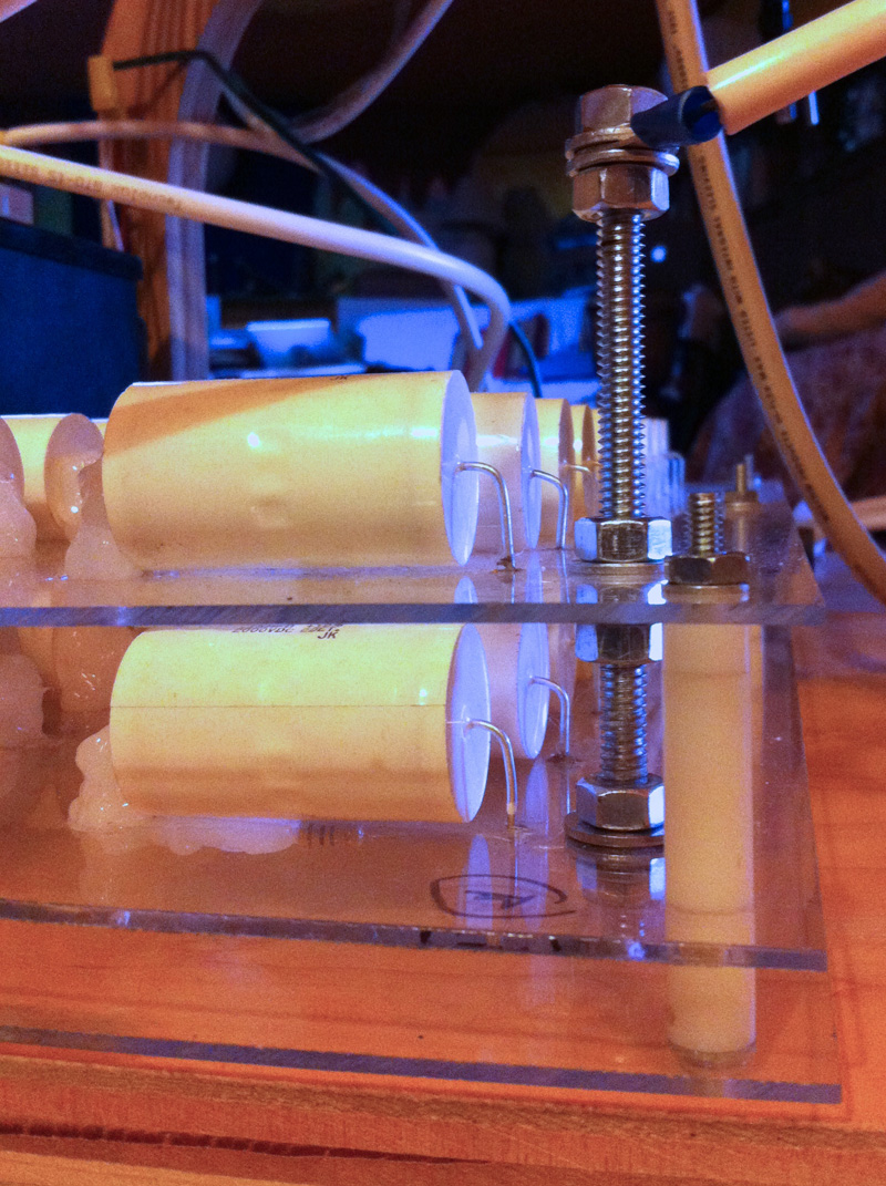
Above: Close-up of the 1/4 inch bolt that connects the two MMC modules in parallel. It is also the contact post for the wires connected to the MMC. This bolt can still get warm after playing with the Tesla coil for a while. If you build this MMC, I recommend using 1/4 inch brass bolts, washers and nuts for the posts, as brass is a better electrical conductor than steel.
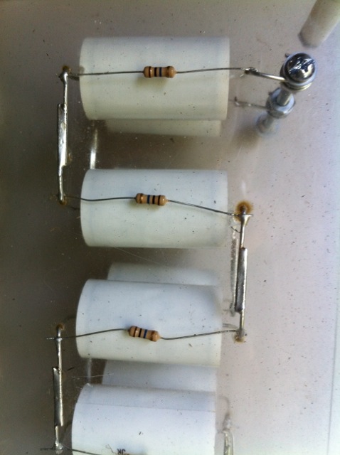
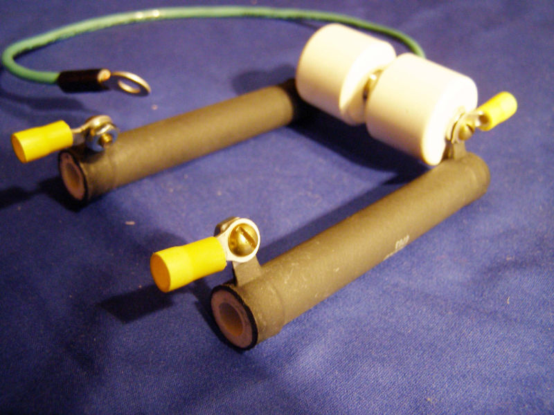
Above: 10 mega ohm 1/2 Watt resistors are soldered across all capacitors in the MMC in order to discharge the caps within seconds after the TC is turned off.
Above: This shows the bridge that connects the two sides of the MMC
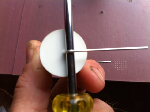
Above: The leads of the individual capacitors are given a radius using a thin round object. A jeweler's screwdriver is perfect
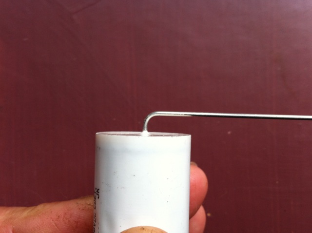
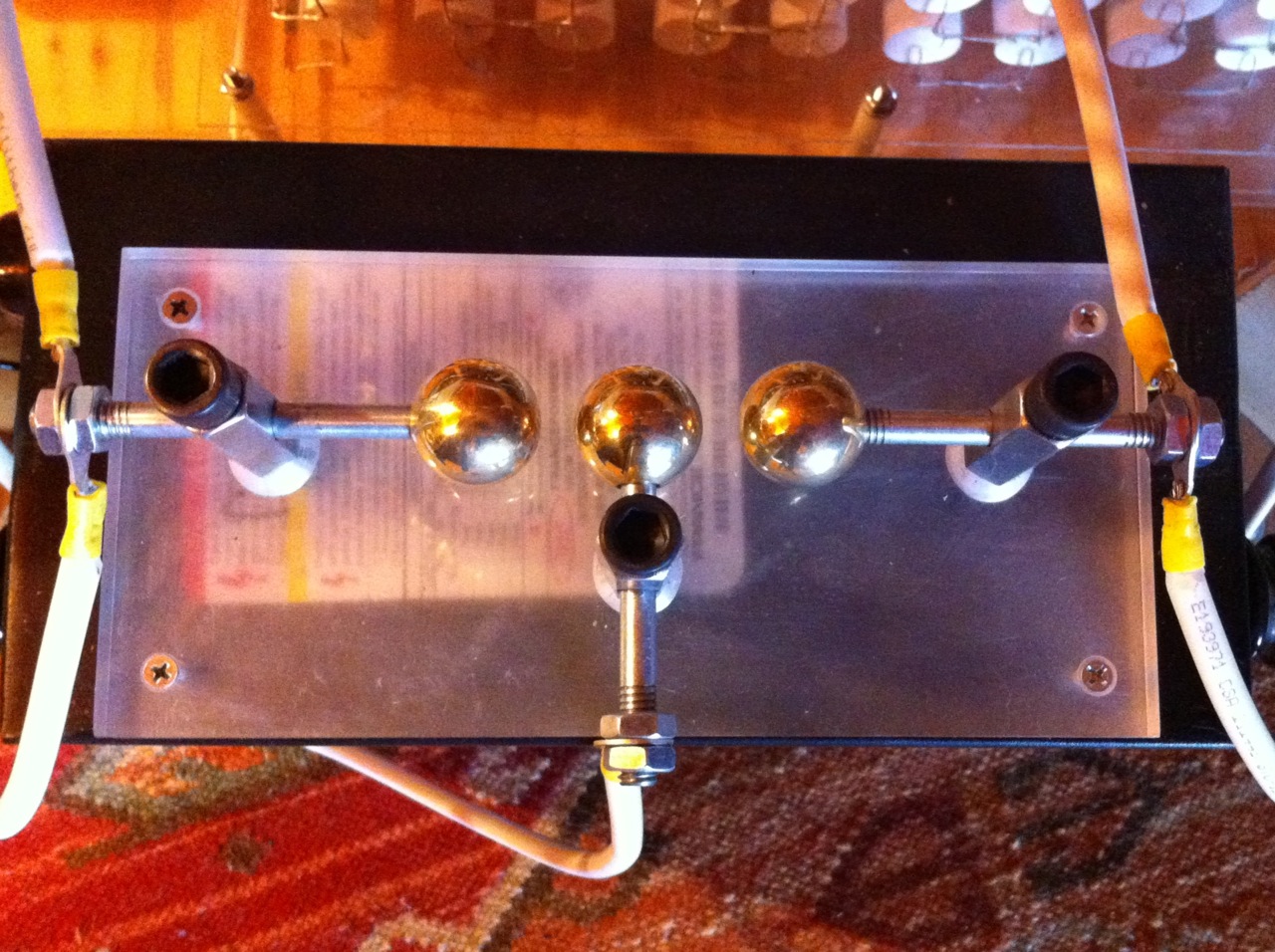
Above: Capacitor electrode with radius The Safety Gap After I fried my first NST within the first five minutes of operation, I installed a safety gap going across the capacitor. OK, let's back up for a second. I no longer use a safety gap across the capacitor. I use a three point safety that sits between the high voltage terminals of the NST. In fact as one can see in the photo, the new safety gap is sitting right on top of the power supply. The base is made of two pieces of 1/2 inch Plexiglas. The center electrode connects to the NST ground. The other two electrodes connect to the two high voltage terminals of the NST. The threaded rod couplings are held in place by countersunk machine screws protruding up through the first layer of Plexiglas. The second layer of Plexiglas acts as an insulator. The two layers of Plexiglas are fastened together by four beveled and countersunk sheet metal screws. I used 5/16 inch steel bolts purchased at Home Depot for the electrodes. The holes drilled into the couplings where just large enough for the "unthreaded" part of the bolt to fit through. The three 5/16 18 solid brass threaded knobs where screwed onto one end of each electrode. I used a 5/16 18 dye to thread the other end of the bolt after I cut the head off with a hack saw and ground the edge smooth. Because the threaded portion of the bolt is has a larger diameter than the unthreaded portion, the threads will not be as deep. Thread about 9/16 of an inch and use that end to screw the brass balls onto. Use the factory threads for the nuts used to tighten the wires to the electrodes. The spark gap distance is about 5/16 of an inch. Just enough so the NST does not ark to ground while the machine is in operation.. Thumb screws are used through the top of the couplings to hold the electrodes in place.
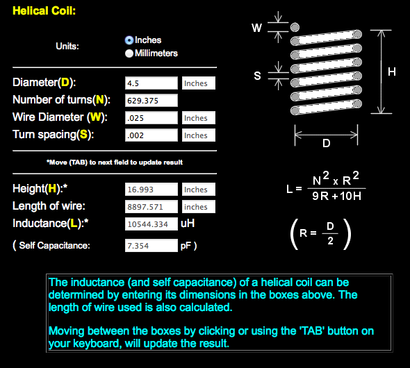
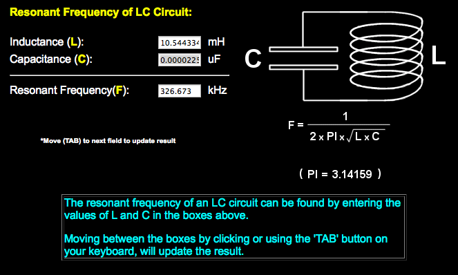
Capacitance CalculationI know that at the beginning of this page I talked about not confusing people with mathematics. HOWEVER, .... if one truly wishes to gain a clearer understanding as to how Tesla coils work, then a little bit of math can't be avoided. I have done my best to make it as understandable as possible. If you have had high school algebra or Algebra 101 in college, the equations below should be easy to understand. The Java Script calculator below, makes calculating the appropriate capacitor size for your Tesla coil very easy and fast. The default calculation is set for a 15000V 60mA power supply. One can change the values in the text fields to match the specifications of your power supply. After changing values, simply click on the last field to update the results. If one wishes to calculate the ideal MMC capacitance with a standard calculator, please see the equasion below. 60Hz is the frequency of our Line Voltage π (Pi) = 3.14159265358979 C (Capacitance) = 1 1 (2π * 60Hz * 15000V / 0.06A) 94247779.6076938 Based on this calculation, .0106uF "SHOULD" be the capacitance of my MMC. Mine and Beachley's MMC is calculated to be .015 MFD which is a little higher than what was recommended by the above formula. How to calculate the capacitance of capacitors connected in series: In order to better visualize what a Series Configuration looks like, imagine a string of 10 children hand in hand, where each child's right hand is held by the left hand of the child to it's right and so on. All the children are facing forward. Now imagine that each child is a capacitor. This is considered a Series Configuration. When capacitors are hooked up in series, the voltage rating of each capacitor is added together to create a combined voltage rating that is equal to the sum of all of the the capacitors. This is just related to voltage. The general misconception is that the capacitance does not change in a series configuration. This is incorrect. The capacitance for individual capacitors hooked up in a series string actually drops significantly. There is a formula to calculate this below. The formula to calculate the combined capacitance of capacitors hooked up in series is as follows: 1/.15 + 1/.15 + 1/.15 + 1/.15 + 1/.15 + 1/.15 + 1/.15 + 1/.15 + 1/.15 + 1/.15 + Total capacitance of each string of 20 capacitors = 1/133.33 = .0075 MFD Connecting capacitors in parallel: When capacitors are hooked up in parallel, add the value of each capacitor to arrive at the total capacitance. In order to visualize what a Parallel Configuration looks like, imagine a line of 10 children with their arms slightly outstretched. Each child standing in front of the other facing the same direction. Add a long rope that connects all ten children with their left hands. Now add another rope connecting all of the children's right hands. Now imagine that each child is a capacitor and that the rope connecting the children on either side is a copper wire. This is a parallel configuration. The capacitance of the MMC used in this Tesla coil is 0.015 MFD OK, to confuse matters a little, here is a link to another web page that calculates our tank capacitor to be 0.02 MFD. Click Here Which one is correct? How much difference does it make? The Primary Coil
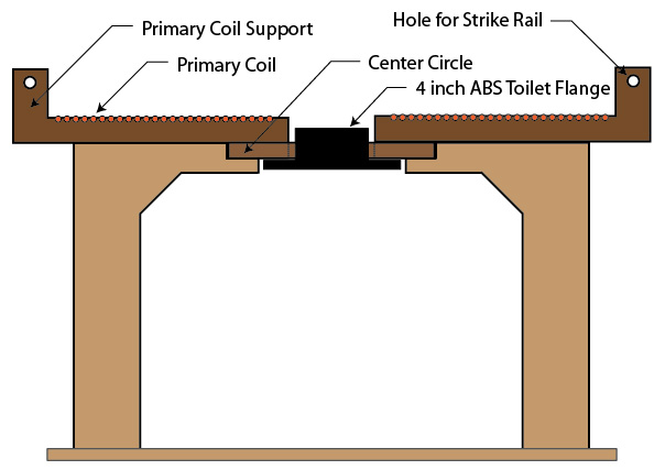
I will soon be building a new primary coil for my Tesla coil. As soon as that happens, I will post photos to go with the text. The cunstruction of the primary coil involves two basic steps; making the base to hold the primary and secondary coils and then cutting the four supports that actually hold the copper tubing for the primary coil in place. It may be easier to design and construct the entire support structure for your tesla coil before beginning this step. The wooden framework for my Tesla coil consists basically of two support levels and is constructed entirely of 3/4 inch plywood. The first level holds the NST, MMC, HV filter, and the spark gap. The second level is created by four risers that are positioned just in from the four corners and are pointing towards the center. Each of these four risers along with the center circle will be the foundation for the the primary and secondary coils. There are many ways to build the support structure for your Tesla coil. Looking at the photos on this page will give you a pretty good idea as to how I designed and built the support structure for my tesla coil. To help the reader under stand what I'm talking about, I drew up the image below on the computer. The lower platform was cut to 23 inches square (recommend 25"). The four main risers for the upper support surface were cut to 9.5 X 11 3/4 inches. Your measurements may vary. The center for the top surface is an 11 inch circle. See diagram below. Enough space must be provided around the toilet flange protruding through the bottom of the center circle for the PVC pipe to fit completely down on top of it.
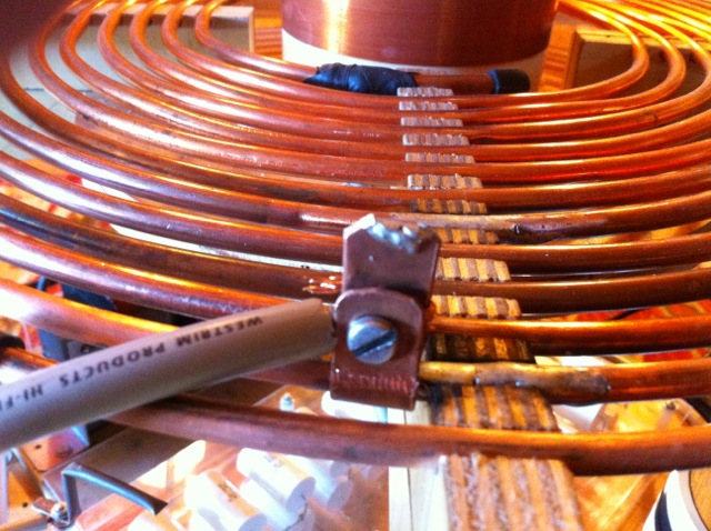
The primary coil generates the magnetic flux needed to allow all of your components to work together. As current is pushed through the primary coil, it will resonate at a certain frequency, coupling it to your secondary coil. It is necessary to be able to tune this resonance for the best results, so I took that into consideration when coming up with this design. Your first step should be to acquire a 50' roll of 1/4" copper refrigeration tubing. This kind of tubing can be found at Home Depot or at online vendors like ebay, if you prefer. Be careful when working with the tubing, it can be easily kinked. When you purchase the tubing it will be wound into a circle, do not unwind it. Instead, you will use this shape to your advantage and gently start to spread the layers of copper tubing apart to form your coil. Each turn of the coil is going to need to be separated by a 1/4" gap. In order to accomplish this make 4 plywood support braces measuring 5 inches X 12 inches each. Please use high grade plywood for this purpose. One can see in the diagram above that the center line for the row of orange holes is set below the surface of the wood. Because of this, the opening in the wood above each hole is less than the outside diameter of the tubing. This is intentional and when the time is right you will actually snap the tubing in place. You will need to use a drill press and a table saw for this process. 1. To start, measure 1.5" up from the bottom of each piece and extended a line down the entire length. 2. Next number pieces, 1, 2, 3 and 4. 3. On all pieces make a line across the width at 2 inches. This will mark the area reserved for the strike rail. 4. On piece #1 now on the opposite end, draw a line across the width at .5 inches. Then continue to make lines in the same fashion every 1/4" until one reaches the line that was drawn on the opposite end (10 inches). 5. Next, make an "X" between the first two vertical lines drawn in the previous step. I then leave a gap and make an "X" in between the next set of vertical lines, continuing this pattern until one reaches the end. 6. Finally, using a drill press along with a fence clamped to the table, drill a 9/32 of an inch hole at the line wherever there is an "X". For greater accuracy and cleaner results start with a small drill bit like 1/8 of an inch and then expand the hole to 9/32. It is important to work slowly and be precise when drilling these holes. For cleaner looking holes, place a piece of scrap wood under your work. 7. Follow the same procedure on pieces 2, 3 and 4 , except that on piece 2, the first line is made at .625" in., On piece 3 at .75" in., and on piece 4 at .875" in. Feel free to download a printable template in png format for these measurements. 8. One will notice that the first vertical line of each piece is offset 1/16". This way, as the copper tubing makes one complete turn, it will form a 1/4" gap between rows. 9. Now using a table saw one will cut just enough off of the top of the holes that were just drilled so that one can snap the 1/4 inch tubing into place. Stop about 1 1/2 inches before our line at two inch mark, turn the saw off, and cut the rest with a hand saw or band saw. If one does not cut deeply enough the tubing will be too difficult to snap in place. Cut too deeply and there will not be enough wood to hold the tubing in place. I like to use a test piece to set the fence distance from the holes. That way one reduces the chances of ruining a good piece of wood. The copper tubing should fit nice and snug into the holes. Occasionally one might need to used a dab of hot glue for extra support. 11. All four of our coil supports should have the same dimensions. Now lets determine where the hole will be for the strike rail. The strike rail will be made of 3/8 inch copper tubing. Measure down 1 inch and place a mark directly in the center (see Hole for Strike Rail in diagram above). Using a 1/2 inch brad point drill bit drill a hole in this location on each of the four supports. The next step needs to take place after the Tesla coil's support structure has been completed. Attaching the Primary Coil Supports to the Base and Winding the Primary Coil 12. With your secondary coil in position over the toilet flange, place primary support #1 in place. Position it so that the copper tubing spiral begins at 7/8 of an inch from the secondary coil surface. Using a pencil, make a mark where the support meets the base. Make a mark in the same location for the other three supports. Next glue support #1 into place with hot melt glue, holding it in position until the glue has cooled. Remove any excess glue with a utility knife. Now one needs to determine the direction of the winds. One might want to consider winding the primary in the same direction as the secondary. Mine is not wound in the same direction and it works just fine. Once one has determined the direction of the winding, go ahead and glue support 2, 3 and 4 into place. 13. Before attempting to snap the primary coil into place, be sure to figure out how you want to come up through the center circle to tie the wire coming from the spark gap to the first turn of the primary. One can see in the photo below that I drilled a hole in the center circle in order to bring the wire up from below and connect to the primary. The wire simply has a long stripped lead that is wrapped around the copper tubing several times and is fastened into place with rubber splicing tape. 13. Now take the 50 foot role of 1/4 inch copper tubing and place it over the secondary and onto the Primary coil supports. The beginning of the coil will start at the support with the .5 Inch mark. See image below. Note: Soft copper tubing is very flexible but only for one or two bends and then it gets stiff very quickly. This is called work hardening. If your copper tubing for some reason has gotten so stiff that it is unbendable without kinking it or breaking it, then you can heat the tubing up with a propane torch, getting it red hot. Once it has cooled down, it will be soft again. Next the tubbing will snap into the next support that has it's first hole drilled at .625 inch. Then it will snap into the support that has its first hole at .75 inch. Finally to complete the first turn, snap the tubing into the 4th support that had its first hole drilled at .875 inch. Continue the process until the entire coil is created. You will discover that if executed slowly and patiently, that the tubing bends and adjusts easily and you will be able to wind the entire coil with relative ease. When creating the strike rail, it is very important that the copper tubing does not form a complete circle. If it does, it could throw off the resonance of the primary. One should be able to purchase just enough 3/8 inch copper tubing from the local hardware store to make the strike rail. That tubing will simply feed through the four holes to make a mostly complete circle. Leave about and inch between the two ends. When wiring up the tesla coil, you will attach a ground wire to it and tape it up with rubber splicing tape like was done on the first wind of the primary coil. Attaching the Copper Tubing to the Primary Coil Supports
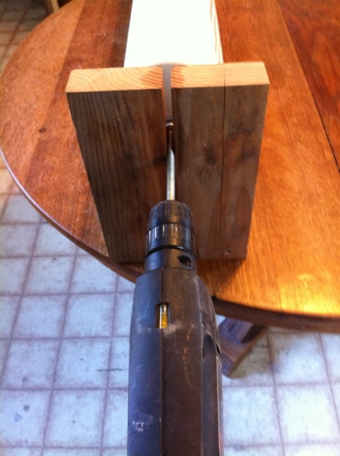
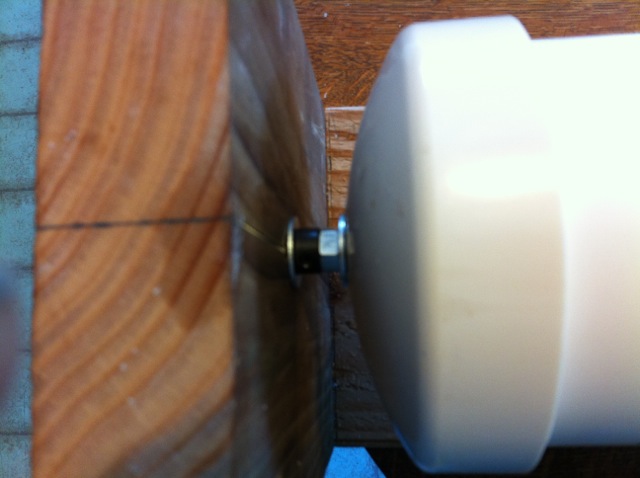
Above: Close-up of how I came up through the wood below to meet the primary at the beginning of the first wind. I wrapped the wire around the copper tubing and then secured it with rubber electrical splicing tape. The Secondary CoilI followed thegeekgroup.org Tesla videos to learn how to build the secondary coil and to build the winding jig. They show you how to build the winding jig, but then later wind the secondary coil using a CNC Lathe. If you can forget that they are using a CNC lathe and just pretend they are using the winding jig they showed you how to build in an earlier video, you will be OK. I also actually believe the drill motor works better than the CNC lathe for winding the secondary coil.. Use your finger as a guide for the magnet wire. Your sense of touch is as important as your eyes in this procedure. If a wire crosses over, you will feel it right away and you can back up to correct the overlap. In thegeekgroup videos, they apply a helix of double sided scotch tape onto the PVC tube prior to winding. This does a very good job of holding the magnet wire in place and keeping it taught and from slipping as you do your wind. All will be revealed when you watch the videos.
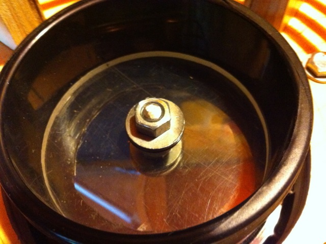
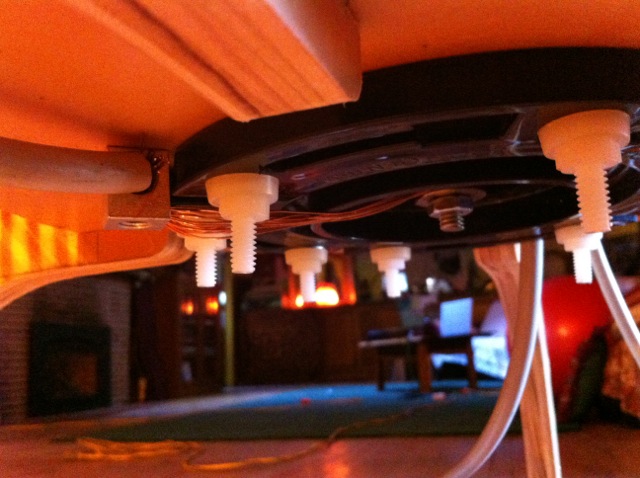
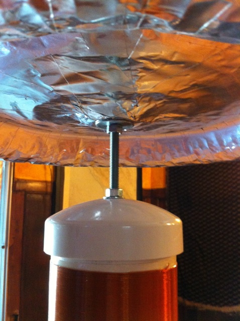
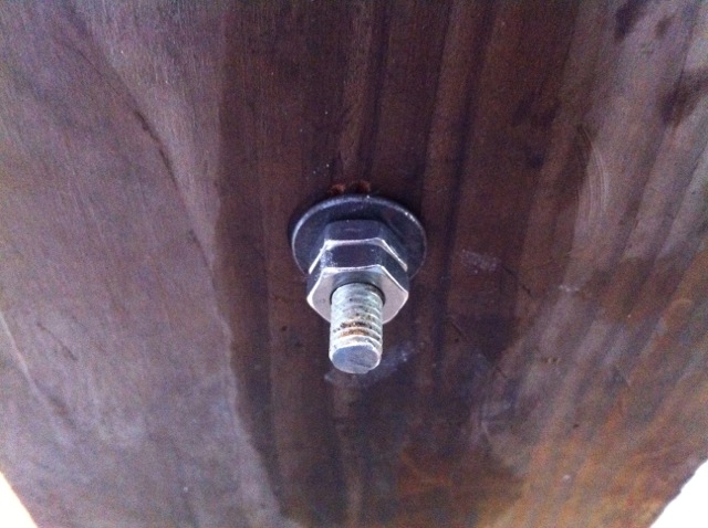
Above: A view of the 4" toilet ABS flange that is protruding through a hole in the wood floor below. The Toilet flange is bolted to the bottom of the floor below using 1/4" nylon screws and washers. Get a toilet flange that has a test plug in it. As you can see in the above image, the test plug is serving as a base for a 1/4" acrylic disc that is resting on top. The acrylic disk has a 5/16" bolt running through the middle of it. The absolute minimum should be protruding into the tube for the secondary coil when it is in place! The bolt and washer shown in the above photo is used to connect the wire coming from the bottom of the secondary coil. View of the toilet flange from the bottom. One can see the ground wire that is attached to the bottom of the bolt. One can also see the wire from the secondary coil that is on the other side of the clear acrylic insulator.
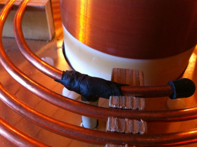
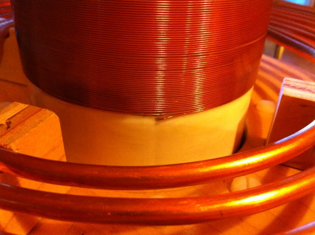
Above: View showing how the wire for the secondary coil goes through a small hole to the inside of the tube. Note how the bottom of the secondary coil is at the same level as the primary coil. Note: Observe that the secondary coil and the primary coil are wound in the same direction. I never here anyone talk about that, but I am fairly sure this little detail is important.
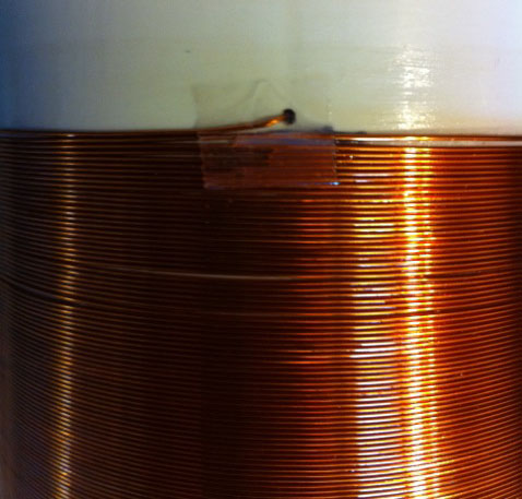
Above: This photo shows the use of a piece of tape to hold the secondary coil wire in place for winding and finishing. After the first coat of finish, one can peal the tape off. There seems to be some argument as to weather or not it is best to keep the secondary wires on the outside or inside. I keep mine on the inside for appearance purposes.
Above: A nice view showing the 1/4" nylon screws used to secure the toilet flange to the wood above. The grounding lug for the secondary is also visible and is attached right next to the toilet flange. From the lug, you can see a HV NST wire that goes to ground. The wire coming off of the bottom of the secondary coil goes to ground.
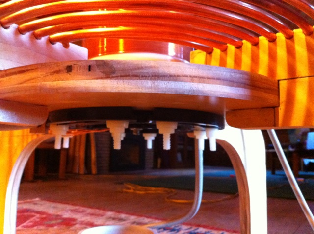
Above: Another really nice view showing how I constructed the support mechanism for the primary and secondary coils, allowing maximum access to the primary coil. The circular piece of wood you see is the actual base for the secondary coil support. It is held in place with hot-melt glue and by the base for the primary coil. No nails or metal screws were used in this area. One can see the 1/4" nylon screws I used to fasten the toilet flange to the secondary coil's base. The Top load or Toroid
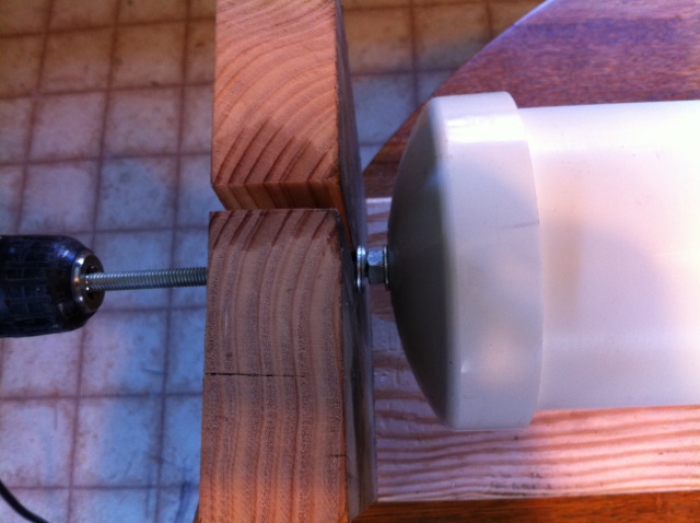
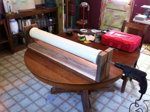
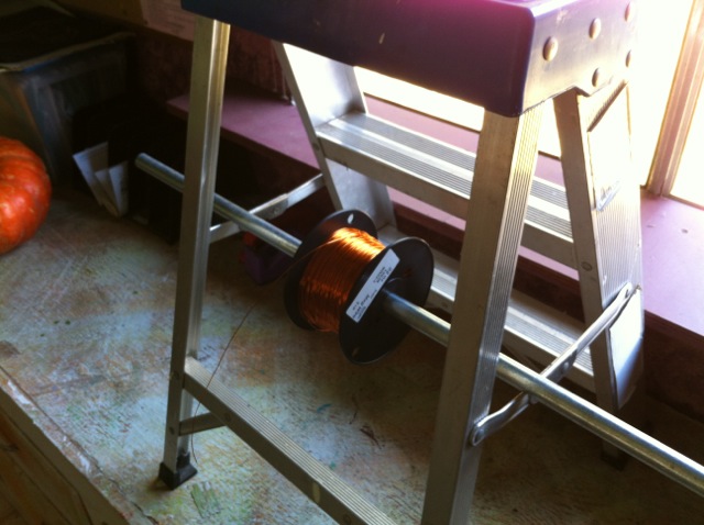
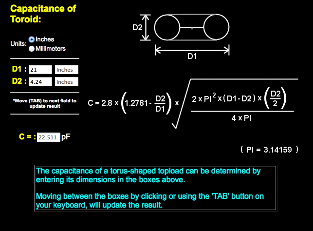
Above: Following the thegeekgroup's instruction video, I created my top load using a 20" bicycle rim, a large box of 4" flexible dryer duct (15'), a large role aluminum duct tape and 1 role of electrical tape. It works surprisingly well. You will notice that the 4" cap is shorter than what you would normally see at the hardware store. I carefully trimmed it off using a table saw. I left 1" of contact surface on the inside of the cap. This is offers plenty support for the toroid, but at the same time makes it easier to get it on and off. If you try this on your own, for sure, wear safety glasses, keep your blade as low as possible, and watch your fingers. It was the only way I could think of to get a perfectly smooth cut. The Toroid should be between 4 and 6 inches above the secondary coil. I removed the original axel and bearings out of the bicycle rim and replaced them with 5/16' threaded rod that was tightened into place with washers and nuts. You can see in the photo above that I used a fender washer and bolt over the aluminum tape to finish the toroid. Every piece of tape going across the bicycle rim went over the CENTER axel. I had to cut a hole into the center of the tape for every piece. In the thegeekgroup video, the Chris Boden applies the tape around the axel. I did not like that. When you watch the video, you will know what I'm talking about. If I were to do it again, I would build a different toroid (click on link) using a more rigid fllexible aluminum duct and two aluminum plates. It will be cheaper and much faster to build! The only thing I would do differently is to use a metal threaded rod instead of Nylon for use with my coil. http://www.youtube.com/watch?v=z30RFaJ2bY8 The Winding JigThe next few images are of my secondary coil winding jig. I got the idea from thegeekgroup.org videos. It worked flawlessly. You need one person to help wind the coil.
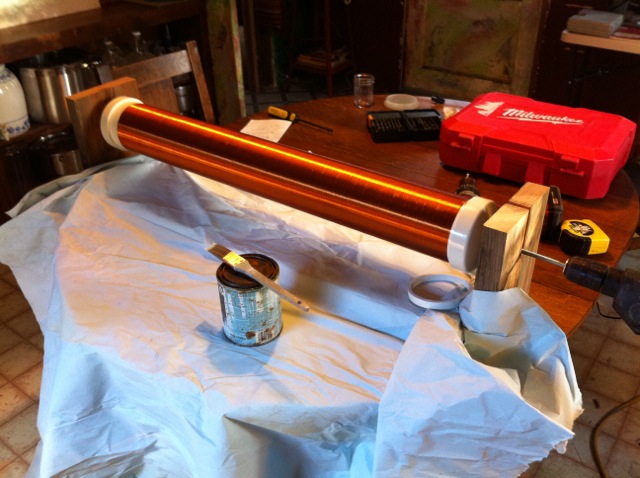
Above: My secondary coil shortly after it was wound and the first coat of polyurethane had been applied. To apply the finish, run the drill motor at low speed and paint (or spay) the finish on with a brush. This is a fantastic way to apply the finish to the secondary coil. Once a new coat of finish has been applied, one can simply set the drill motor on low speed and tape the trigger in place so it will keep the secondary coil turning on its own. The weight of the drill motor handle, keeps the drill motor from spinning around. I applied some mineral oil in the places where threaded rod touches the wood for lubrication. To complete the job, I put 10 coats of polyurethane onto my secondary winding.
|
| American Wire Gauge (AWG) |
Diameter (inches) |
Diameter (mm) |
Cross Sectional Area (mm2) |
| 0000 | 0.46 | 11.68 | 107.16 |
| 000 | 0.4096 | 10.40 | 84.97 |
| 00 | 0.3648 | 9.27 | 67.40 |
| 0 | 0.3249 | 8.25 | 53.46 |
| 1 | 0.2893 | 7.35 | 42.39 |
| 2 | 0.2576 | 6.54 | 33.61 |
| 3 | 0.2294 | 5.83 | 26.65 |
| 4 | 0.2043 | 5.19 | 21.14 |
| 5 | 0.1819 | 4.62 | 16.76 |
| 6 | 0.162 | 4.11 | 13.29 |
| 7 | 0.1443 | 3.67 | 10.55 |
| 8 | 0.1285 | 3.26 | 8.36 |
| 9 | 0.1144 | 2.91 | 6.63 |
| 10 | 0.1019 | 2.59 | 5.26 |
| 11 | 0.0907 | 2.30 | 4.17 |
| 12 | 0.0808 | 2.05 | 3.31 |
| 13 | 0.072 | 1.83 | 2.63 |
| 14 | 0.0641 | 1.63 | 2.08 |
| 15 | 0.0571 | 1.45 | 1.65 |
| 16 | 0.0508 | 1.29 | 1.31 |
| 17 | 0.0453 | 1.15 | 1.04 |
| 18 | 0.0403 | 1.02 | 0.82 |
| 19 | 0.0359 | 0.91 | 0.65 |
| 20 | 0.032 | 0.81 | 0.52 |
| 21 | 0.0285 | 0.72 | 0.41 |
| 22 | 0.0254 | 0.65 | 0.33 |
| 23 | 0.0226 | 0.57 | 0.26 |
| 24 | 0.0201 | 0.51 | 0.20 |
| 25 | 0.0179 | 0.45 | 0.16 |
| 26 | 0.0159 | 0.40 | 0.13 |
| uF/ MFD | nF | pF/ MMFD | uF/ MFD | nF | pF/ MMFD | |
| 1uF / MFD | 1000nF | 1000000pF(MMFD) | 0.001uF / MFD | 1nF | 1000pF(MMFD) | |
| 0.82uF / MFD | 820nF | 820000pF (MMFD) | 0.00082uF / MFD | 0.82nF | 820pF (MMFD) | |
| 0.8uF / MFD | 800nF | 800000pF (MMFD) | 0.0008uF / MFD | 0.8nF | 800pF (MMFD) | |
| 0.7uF / MFD | 700nF | 700000pF (MMFD) | 0.0007uF / MFD | 0.7nF | 700pF (MMFD) | |
| 0.68uF / MFD | 680nF | 680000pF (MMFD) | 0.00068uF / MFD | 0.68nF | 680pF (MMFD) | |
| 0.6uF / MFD | 600nF | 600000pF (MMFD) | 0.0006uF / MFD | 0.6nF | 600pF (MMFD) | |
| 0.56uF / MFD | 560nF | 560000pF (MMFD) | 0.00056uF / MFD | 0.56nF | 560pF (MMFD) | |
| 0.5uF / MFD | 500nF | 500000pF (MMFD) | 0.0005uF / MFD | 0.5nF | 500pF (MMFD) | |
| 0.47uF / MFD | 470nF | 470000pF (MMFD) | 0.00047uF / MFD | 0.47nF | 470pF (MMFD) | |
| 0.4uF / MFD | 400nF | 400000pF (MMFD) | 0.0004uF / MFD | 0.4nF | 400pF (MMFD) | |
| 0.39uF / MFD | 390nF | 390000pF (MMFD) | 0.00039uF / MFD | 0.39nF | 390pF (MMFD) | |
| 0.33uF / MFD | 330nF | 330000pF (MMFD) | 0.00033uF / MFD | 0.33nF | 330pF (MMFD) | |
| 0.3uF / MFD | 300nF | 300000pF (MMFD) | 0.0003uF / MFD | 0.3nF | 300pF (MMFD) | |
| 0.27uF / MFD | 270nF | 270000pF (MMFD) | 0.00027uF / MFD | 0.27nF | 270pF (MMFD) | |
| 0.25uF / MFD | 250nF | 250000pF (MMFD) | 0.00025uF / MFD | 0.25nF | 250pF (MMFD) | |
| 0.22uF / MFD | 220nF | 220000pF (MMFD) | 0.00022uF / MFD | 0.22nF | 220pF (MMFD) | |
| 0.2uF / MFD | 200nF | 200000pF (MMFD) | 0.0002uF / MFD | 0.2nF | 200pF (MMFD) | |
| 0.18uF / MFD | 180nF | 180000pF (MMFD) | 0.00018uF / MFD | 0.18nF | 180pF (MMFD) | |
| 0.15uF / MFD | 150nF | 150000pF (MMFD) | 0.00015uF / MFD | 0.15nF | 150pF (MMFD) | |
| 0.12uF / MFD | 120nF | 120000pF (MMFD) | 0.00012uF / MFD | 0.12nF | 120pF (MMFD) | |
| 0.1uF / MFD | 100nF | 100000pF (MMFD) | 0.0001uF / MFD | 0.1nF | 100pF (MMFD) | |
| 0.082uF / MFD | 82nF | 82000pF (MMFD) | 0.000082uF / MFD | 0.082nF | 82pF (MMFD) | |
| 0.08uF / MFD | 80nF | 80000pF (MMFD) | 0.00008uF / MFD | 0.08nF | 80pF (MMFD) | |
| 0.07uF / MFD | 70nF | 70000pF (MMFD) | 0.00007uF / MFD | 0.07nF | 70pF (MMFD) | |
| 0.068uF / MFD | 68nF | 68000pF (MMFD) | 0.000068uF / MFD | 0.068nF | 68pF (MMFD) | |
| 0.06uF / MFD | 60nF | 60000pF (MMFD) | 0.00006uF / MFD | 0.06nF | 60pF (MMFD) | |
| 0.056uF / MFD | 56nF | 56000pF (MMFD) | 0.000056uF / MFD | 0.056nF | 56pF (MMFD) | |
| 0.05uF / MFD | 50nF | 50000pF (MMFD) | 0.00005uF / MFD | 0.05nF | 50pF (MMFD) | |
| 0.047uF / MFD | 47nF | 47000pF (MMFD) | 0.000047uF / MFD | 0.047nF | 47pF (MMFD) | |
| 0.04uF / MFD | 40nF | 40000pF (MMFD) | 0.00004uF / MFD | 0.04nF | 40pF (MMFD) | |
| 0.039uF / MFD | 39nF | 39000pF (MMFD) | 0.000039uF / MFD | 0.039nF | 39pF (MMFD) | |
| 0.033uF / MFD | 33nF | 33000pF (MMFD) | 0.000033uF / MFD | 0.033nF | 33pF (MMFD) | |
| 0.03uF / MFD | 30nF | 30000pF (MMFD) | 0.00003uF / MFD | 0.03nF | 30pF (MMFD) | |
| 0.027uF / MFD | 27nF | 27000pF (MMFD) | 0.000027uF / MFD | 0.027nF | 27pF (MMFD) | |
| 0.025uF / MFD | 25nF | 25000pF (MMFD) | 0.000025uF / MFD | 0.025nF | 25pF (MMFD) | |
| 0.022uF / MFD | 22nF | 22000pF (MMFD) | 0.000022uF / MFD | 0.022nF | 22pF (MMFD) | |
| 0.02uF / MFD | 20nF | 20000pF (MMFD) | 0.00002uF / MFD | 0.02nF | 20pF (MMFD) | |
| 0.018uF / MFD | 18nF | 18000pF (MMFD) | 0.000018uF / MFD | 0.018nF | 18pF (MMFD) | |
| 0.015uF / MFD | 15nF | 15000pF (MMFD) | 0.000015uF / MFD | 0.015nF | 15pF (MMFD) | |
| 0.012uF / MFD | 12nF | 12000pF (MMFD) | 0.000012uF / MFD | 0.012nF | 12pF (MMFD) | |
| 0.01uF / MFD | 10nF | 10000pF (MMFD) | 0.00001uF / MFD | 0.01nF | 10pF (MMFD) | |
| 0.0082uF / MFD | 8.2nF | 8200pF (MMFD) | 0.0000082uF / MFD | 0.0082nF | 8.2pF (MMFD) | |
| 0.008uF / MFD | 8nF | 8000pF (MMFD) | 0.000008uF / MFD | 0.008nF | 8pF (MMFD) | |
| 0.007uF / MFD | 7nF | 7000pF (MMFD) | 0.000007uF / MFD | 0.007nF | 7pF (MMFD) | |
| 0.0068uF / MFD | 6.8nF | 6800pF (MMFD) | 0.0000068uF / MFD | 0.0068nF | 6.8pF (MMFD) | |
| 0.006uF / MFD | 6nF | 6000pF (MMFD) | 0.000006uF / MFD | 0.006nF | 6pF (MMFD) | |
| 0.0056uF / MFD | 5.6nF | 5600pF (MMFD) | 0.0000056uF / MFD | 0.0056nF | 5.6pF (MMFD) | |
| 0.005uF / MFD | 5nF | 5000pF (MMFD) | 0.000005uF / MFD | 0.005nF | 5pF (MMFD) | |
| 0.0047uF / MFD | 4.7nF | 4700pF (MMFD) | 0.0000047uF / MFD | 0.0047nF | 4.7pF (MMFD) | |
| 0.004uF / MFD | 4nF | 4000pF (MMFD) | 0.000004uF / MFD | 0.004nF | 4pF (MMFD) | |
| 0.0039uF / MFD | 3.9nF | 3900pF (MMFD) | 0.0000039uF / MFD | 0.0039nF | 3.9pF (MMFD) | |
| 0.0033uF / MFD | 3.3nF | 3300pF (MMFD) | 0.0000033uF / MFD | 0.0033nF | 3.3pF (MMFD) | |
| 0.003uF / MFD | 3nF | 3000pF (MMFD) | 0.000003uF / MFD | 0.003nF | 3pF (MMFD) | |
| 0.0027uF / MFD | 2.7nF | 2700pF (MMFD) | 0.0000027uF / MFD | 0.0027nF | 2.7pF (MMFD) | |
| 0.0025uF / MFD | 2.5nF | 2500pF (MMFD) | 0.0000025uF / MFD | 0.0025nF | 2.5pF (MMFD) | |
| 0.0022uF / MFD | 2.2nF | 2200pF (MMFD) | 0.0000022uF / MFD | 0.0022nF | 2.2pF (MMFD) | |
| 0.002uF / MFD | 2nF | 2000pF (MMFD) | 0.000002uF / MFD | 0.002nF | 2pF (MMFD) | |
| 0.0018uF / MFD | 1.8nF | 1800pF (MMFD) | 0.0000018uF / MFD | 0.0018nF | 1.8pF (MMFD) | |
| 0.0015uF / MFD | 1.5nF | 1500pF (MMFD) | 0.0000015uF / MFD | 0.0015nF | 1.5pF (MMFD) | |
| 0.0012uF / MFD | 1.2nF | 1200pF (MMFD) | 0.0000012uF / MFD | 0.0012nF | 1.2pF (MMFD) | |
| 0.001uF / MFD | 1nF | 1000pF (MMFD) | ………. | 0.000001uF / MFD | 0.001nF | 1pF (MMFD) |
Modifications
05/01/2013
Spark Gap Change & Additional 15KV 60mA NST
Above: It seems we get used to what we have very quickly and I found myself longing for bigger sparks. Well according to thegeekgroup.org, the only way to accomplish that is to add more power to your system with an additional NST. The NST must be rated exactly the same as the other! In my case I added another 15,000V 60mA NST to my Tesla coil circuit. The NST must also be hooked up in parallel. That means unless the two transformers are identical models from the same company, it will be necessary to phase your transformers. Instructions for phasing neon sign transformers can be found on the thegeekgroup.org videos. After I added the new NST, I only had to adjust the safety gap. Everything else seemed perfect. The results of adding another transformer are amazing, greatly increasing the length and thickness of the streamers. I'm currently back to running my Tesla coil with one NST. The depotted NST you see above died some time ago.
12/14/2013
New Additions Soon To Be Added To My Tesla Ccoil
High frequency high voltage filter to protect the NST. This is not a Terry filter. Hopefully this will prevent my Tesla coil from
frying any more Neon Sign Transformers. I purchased it from Tesla Stuff on Ebay
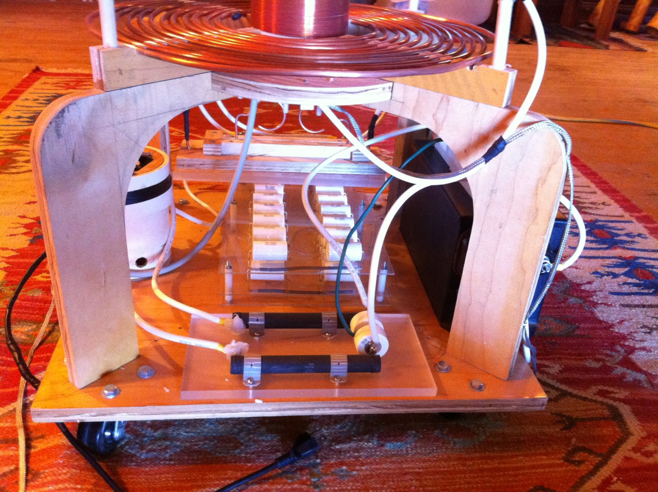
Here it is installed. I was having some HV flash-over problems between contacts on the HV filter and between the rows of capacitors on the MMC. The problem was not caused by the filter, but that is why you see some silicone around two of the filter's contacts. The flash-over problem was caused by other modifications I was attempting on the MMC and the spark gap.
Correction to this diagram. The diagram shows the neutral side of the MOT's primary connections leading directly to ground. In essence this is correct. However to be compliant with modern electrical code, the neutral , or return side of the MOT primary windings should really be connected to a white wire that leads to the neutral buss of a sub-panel or to the ground bus of a main entrance panel. This means that a 4 wire cable will be necessary to properly hook this circuit up.
¡Warning Extreme Electrocution Hazard!
08/06/2014 — 240V 4 MOT Tesla Coil Power Supply Test 1
This is my first attempt at building a 4 MOT Tesla coil power supply.The primary coils of the 2 MOT's used as ballast need to be situated in series with the two 120V hot inputs to the circuit. One MOT for each 120V leg. The high voltage output to the secondary coils on the ballast MOT's need to be shorted to their cases. This effectively provides sufficient current reduction for the MOT power supply; perhaps even a little too much. If the ballast MOT's secondary coils are not shorted out to the case (and I do not understand the reason for this), too much induction occurs within the primary coils and the current flow is reduced to almost nothing! I have tried all kinds of variations and this seems to be the only way to ballast a MOT power supply using unaltered MOT's as reactors!
The BIG problem is that the secondary coils on the ballast MOT's get too hot within just a few seconds of operation. In other words, this is not an effective ballasting solution, because one is not given enough time to do any serious work with a tesla coil! Cool down time may be an up to an hour.
My questions Are:
- How does one solve the problem of the ballast MOT's secondary coils from over heating? Anyone out there have the solution?
- Are there any instructions out there that provide a detailed and relatively easy and inexpensive way to create an alternative and perhaps even an adjustable ballast for a MOT power supply?
Please post any questions of solutions on my YouTube channel. Thanks!
08/07/14 Video— Using a 15,000V 60mA NST and the static PVC pipe spark gap that I show how to make in the above tutorial.
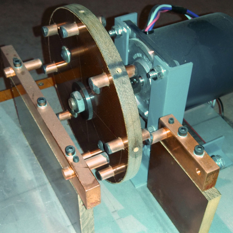
04/15/15 Video — Using 15000V 60mA NST and an 8 point, phase controlled synchronous rotary spark gap (SRSG)
04/15/15 Video — Using 15000V 60mA NST and an 8 point, phase controlled synchronous rotary spark gap (SRSG)
04/15/15 Video — Using 15000V 60mA NST and an 8 point, phase controlled synchronous rotary spark gap (SRSG)